Free EDA Tooling for Amateur Radio
RFSim99
AppCAD
http://www.hp.woodshot.com/
QUCS Studio
http://dd6um.darc.de/QucsStudio/download.html
Autodesk EAGLE
http://eagle.autodesk.com/eagle/release-notes
KiCAD
http://kicad-pcb.org/
VNWA
https://www.sdr-kits.net/DG8SAQ-VNWA-software-documentation-user-guide
free EDA tooling list
2019年5月9日 星期四
2019年2月28日 星期四
SDR and GNURadio Course Outline
Hardware
1. What is Radio ? What is Software Defined Radio ?2. Generalize SDR Architecture
3. The well known SDR platforms
RTL-SDR, plutoSDR, SDRDuo, HackRF, AirSpy HF+, FunCube Dongle Pro+, KX3, IC7610,
Perseus, USRP B205mini, SunSDR2, Flex6500
4. Remote Operation
WebSDR, OpenWebRX
Software
0. Most used SDR software SDR#, HDSDR, SDR-Console, SDRuno, Linrad, gqrx, GNURadio1. What is GNURadio ? What inside of the GNURadio ? What is its capability and Why is it required ?
2. GNU Radio Live SDR Environment (Run without installation)
3. GNURadio installation – Linux and Windows environment
4. GNURadio experiment – examples and practice (basic blocks function and AM/FM radio)
5. Advanced techniques – Out Of Tree (https://wiki.gnuradio.org/index.php/OutOfTreeModules)
6. Q&A and supplements (GRCon and FOSDEM meeting agenda)
FUNcube Dongle Pro+ Block Diagram

HackRF One Block Diagram

SDR Comparison Table

SDR Comparison Table in searchable format
Presentation material: 01_sdr and gnuradio_wjlee20190228_2in1.pdf
(hardware related sheets in black background, software related sheets in blue background and the information related sheets in green background)
GNU Radio Practice
0. GNURadio Installation
a. Linux Installation
From scratch
Install Dependencies(Ubuntu 18.04 LTS or Mint Tara)
sudo apt-get -y install git cmake g++ python-dev swig \
pkg-config libfftw3-dev libboost-all-dev libcppunit-dev libgsl-dev \
libusb-dev libsdl1.2-dev python-wxgtk3.0 python-numpy python-cheetah \
python-lxml doxygen libxi-dev python-sip libqt4-opengl-dev libqwt-dev \
libfontconfig1-dev libxrender-dev python-sip python-sip-dev python-qt4 \
python-sphinx libusb-1.0-0-dev libcomedi-dev libzmq3-dev python-mako \
python-gtk2
Installing GNU Radio
git clone --recursive http://git.gnuradio.org/git/gnuradio.git
cd gnuradio; mkdir build; cd build; cmake ../; make; sudo make install
https://wiki.gnuradio.org/index.php/UbuntuInstall
From repository
sudo apt-get install gnuradio
b. Load Gnuradio Live ISO with Virtual machine
https://www.vmware.com/tw/products/workstation-player/workstation-player-evaluation.html
https://wiki.gnuradio.org/index.php/GNU_Radio_Live_SDR_Environment

c. Burn Gnuradio Live ISO to USB thumb drive or DVDD
Unetbootin location https://unetbootin.github.io/

d. Install GNURadio in Windows
http://www.gcndevelopment.com/gnuradio/downloads.htm
run “*\GNURadio-3.7\bin\volk-profile.exe” to optimization computer performance after the installation
start GnuRadio Companion(GRC)

1. My first project – Function Generator


Used blocks: Options, Variable, Signal Source, Noise Source, Add, Multiple Const, Audio Sink, QT GUI Range, QT GUI Chooser, QT GUI Sink
GRC file: function generator
2. DTMF Tone Generator


Used blocks: Options, Variable, Signal Source, Selector, Add, Multiple Const, Audio Sink, QT GUI Chooser, Throttle, QT GUI Sink, QT GUI Time Sink, Null Source, Null Sink
GRC file: DTMF Tone Generator
3. X-Y Plot


Used Blocks: Option, Variable, Signal Source, QT GUI Range, Float to Complex, Throttle, QT GUI Sink
GRC file: X-Y plot with QT GUI
4. Tunable Bandpass Filter


Used blocks: Options, Variable, Noise Source, Throttle, Band-Pass Filter Taps, Band Pass Filter, FFT Filter, QT GUI Range, QT GUI Sink
GRC file: Tunable Band Pass Filter
5. AM Demod – From USRP recorded signal


6. AM/DSB-SC/USB/LSB Modulation


7. RTL-SDR FM tuner
RTL-SDR driver installation for GNU Radio(Zadig)


Gnuradio experiments collection: gnuradio experiments.zip
Presentation material for the experiment: 02_gnuradio experiments_wjlee20190228_2in1.pdf
Where to find more useful information: 03_grcon and fosdem_20190228_2in1.pdf
0. GNURadio Installation
a. Linux Installation
From scratch
Install Dependencies(Ubuntu 18.04 LTS or Mint Tara)
sudo apt-get -y install git cmake g++ python-dev swig \
pkg-config libfftw3-dev libboost-all-dev libcppunit-dev libgsl-dev \
libusb-dev libsdl1.2-dev python-wxgtk3.0 python-numpy python-cheetah \
python-lxml doxygen libxi-dev python-sip libqt4-opengl-dev libqwt-dev \
libfontconfig1-dev libxrender-dev python-sip python-sip-dev python-qt4 \
python-sphinx libusb-1.0-0-dev libcomedi-dev libzmq3-dev python-mako \
python-gtk2
Installing GNU Radio
git clone --recursive http://git.gnuradio.org/git/gnuradio.git
cd gnuradio; mkdir build; cd build; cmake ../; make; sudo make install
https://wiki.gnuradio.org/index.php/UbuntuInstall
From repository
sudo apt-get install gnuradio
b. Load Gnuradio Live ISO with Virtual machine
https://www.vmware.com/tw/products/workstation-player/workstation-player-evaluation.html
https://wiki.gnuradio.org/index.php/GNU_Radio_Live_SDR_Environment

c. Burn Gnuradio Live ISO to USB thumb drive or DVDD
Unetbootin location https://unetbootin.github.io/

d. Install GNURadio in Windows
http://www.gcndevelopment.com/gnuradio/downloads.htm
run “*\GNURadio-3.7\bin\volk-profile.exe” to optimization computer performance after the installation
start GnuRadio Companion(GRC)

1. My first project – Function Generator


Used blocks: Options, Variable, Signal Source, Noise Source, Add, Multiple Const, Audio Sink, QT GUI Range, QT GUI Chooser, QT GUI Sink
GRC file: function generator
2. DTMF Tone Generator


Used blocks: Options, Variable, Signal Source, Selector, Add, Multiple Const, Audio Sink, QT GUI Chooser, Throttle, QT GUI Sink, QT GUI Time Sink, Null Source, Null Sink
GRC file: DTMF Tone Generator
3. X-Y Plot


Used Blocks: Option, Variable, Signal Source, QT GUI Range, Float to Complex, Throttle, QT GUI Sink
GRC file: X-Y plot with QT GUI
4. Tunable Bandpass Filter


Used blocks: Options, Variable, Noise Source, Throttle, Band-Pass Filter Taps, Band Pass Filter, FFT Filter, QT GUI Range, QT GUI Sink
GRC file: Tunable Band Pass Filter
5. AM Demod – From USRP recorded signal


Used blocks: Options, Variable, File Source, Signal Source, Add, Multiply, Multiply Const, Rational Resampler, Complex To Mag, DC Blocker, Low Pass Filter, QT GUI Range, QT GUI Time Sink, QT GUI Sink, Audio Sink
USRP recorded file: am_usrp710.dat (Dr. Katz course project)
GRC file: AM demodulation from recorded file
6. AM/DSB-SC/USB/LSB Modulation


Used blocks: Options, Variable, Noise Source, Signal Source, Add Const, Multiply, Selector, Low Pass Filter, Band Pass Filter, QT GUI Chooser, QT GUI Time Sink, QT GUI Sink
GRC file: AM/DSB-SC/SSB modulation
7. RTL-SDR FM tuner
RTL-SDR driver installation for GNU Radio(Zadig)


Used blocks: Options, Variable, RTL-SDR Source, Multiply Const, Low Pass Filter, WBFM Receiver, Rational Resampler, QT GUI Range, QT GUI Time Sink, Audio Sink, QT GUI Sink, QT GUI Waterfall Sink
GRC file: RTL-SDR FM TunerGnuradio experiments collection: gnuradio experiments.zip
Presentation material for the experiment: 02_gnuradio experiments_wjlee20190228_2in1.pdf
Where to find more useful information: 03_grcon and fosdem_20190228_2in1.pdf
2018年4月6日 星期五
Black Pill(STM32F103C8T6) to work with Arduino
The Black Pill is a STM32F103C8T6 based controller board with 64K Flash, 20K SRAM, 2x 12-bit ADC, 2x SPI, 2x I2C, 2x USART, 1x USB and 5V-tolerant I/O. It cost 2 to 3 USD from Ebay or Taobao. As its name, Black Pill's PCB color is black and there are different variant called Blue Pill, and Red Pill. From the schematic, you can see the indication LED is connected to PB12. When PB12 is assigned to "0", it will turn-on the LED.


To program the Black Pill, you can use the UART(bootloader) or ST-Link. In addition, you can also use the USB interface, but you need burn the USB bootloader to it in advance. The procedure to work Black Pill with Arduino IDE and USB interface is shown below


To program the Black Pill, you can use the UART(bootloader) or ST-Link. In addition, you can also use the USB interface, but you need burn the USB bootloader to it in advance. The procedure to work Black Pill with Arduino IDE and USB interface is shown below
1. Burn USB Bootloader
a. Set the BOOT1/BOOT0 as 0/1
b. Prepare a USB-2-UART cable and connect PA9/RX, PA10/TX, +3.3V and ground
c. Download and install ST flash loader; download black pill firmware(generic_boot20_pb12.bin)
d. Start ST flasher loader and upload the firmware
** The setting and connection between Black Pill and USB-2-UART cable need assign properly, otherwise the flash loader program will not go the burn process. The connection and operation menu is displayed.
** The setting and connection between Black Pill and USB-2-UART cable need assign properly, otherwise the flash loader program will not go the burn process. The connection and operation menu is displayed.


2. Arduino IDE to support the STM32
a. Get Arduino_STM32 from github and put it over
"C:\Users\<login username>\Documents\Arduino\hardware"
(my example C:\Users\vincentlee\Documents\Arduino\hardware\Arduino_STM32)
b. run "C:\Users\vincentlee\Documents\Arduino\hardware\Arduino_STM32\drivers\win\install_drivers.bat"
to install the driver or you will see error in Arduino upload.
c. Start the Arduino IDE to select and check the Black Pill is supported. The "Get Board Info" menu can show the board information


d. Load the "blink" example, edit the indication LED pin to "PB12" for Black Pill

e. Set the BOOT1/BOOT0=0/0 to boot for flash memory and connect the Black Pill thru USB

f. Compile and upload the Sketch to Black Pill
 If the "blink" Sketch is uploaded properly, it will turn-on the LED for 3 sec and turn-off LED for 1 sec continuously.
If the DFU driver is not installed in procedure 2/b, then the error message
"Couldn't find the DFU device:[1EAF:0003]" is displayed and the upload process failed.

STM = the vendor, STMicroelectronics
32 = 32-bit, i.e. ARM series
F103 = model, “F1” also indicates that this is an ARM Cortex M3
C = 48-pins
8 = flash memory size is 64 KB(B series with 128KB flash and it seems share the same dice as 8 series)
T = package type is LQFP
6 = temperature range -40 to +85 °C
2. BOOT1/BOOT0 selection
From ST's datasheet, it worked as
3. The board's COM port is not shown in programming
Sometimes, the used-to-work Black Pill is not function properly to show the COM port anymore. You can try to reset the board or load again the DFU driver again as procedure 2/b
4. reference link
a. Roger Clark's github
https://github.com/rogerclarkmelbourne
b. stm32duino wiki
http://wiki.stm32duino.com/index.php?title=Black_Pill
http://wiki.stm32duino.com/index.php?title=Blue_Pill
http://wiki.stm32duino.com/index.php?title=Maple_Mini
http://wiki.stm32duino.com/index.php?title=Red_Pill
"C:\Users\<login username>\Documents\Arduino\hardware"
(my example C:\Users\vincentlee\Documents\Arduino\hardware\Arduino_STM32)
b. run "C:\Users\vincentlee\Documents\Arduino\hardware\Arduino_STM32\drivers\win\install_drivers.bat"
to install the driver or you will see error in Arduino upload.
c. Start the Arduino IDE to select and check the Black Pill is supported. The "Get Board Info" menu can show the board information

d. Load the "blink" example, edit the indication LED pin to "PB12" for Black Pill

e. Set the BOOT1/BOOT0=0/0 to boot for flash memory and connect the Black Pill thru USB

f. Compile and upload the Sketch to Black Pill

If the DFU driver is not installed in procedure 2/b, then the error message
"Couldn't find the DFU device:[1EAF:0003]" is displayed and the upload process failed.

Q&A
1. STM32F103C8T6 part number naming ruleSTM = the vendor, STMicroelectronics
32 = 32-bit, i.e. ARM series
F103 = model, “F1” also indicates that this is an ARM Cortex M3
C = 48-pins
8 = flash memory size is 64 KB(B series with 128KB flash and it seems share the same dice as 8 series)
T = package type is LQFP
6 = temperature range -40 to +85 °C
2. BOOT1/BOOT0 selection
From ST's datasheet, it worked as
| Boot mode selection pins | Boot mode | Aliasing | Note | |
| BOOT1 | BOOT0 | |||
| x | 0 | Main Flash memory | Main Flash memory is selected as boot space | USB bootloader burned to work with Arduino IDE |
| 0 | 1 | System memory | System memory is selected as boot space |
USART bootloader |
| 1 | 1 | Embedded SRAM | Embedded SRAM is selected as boot space |
SRAM boot for debug |
3. The board's COM port is not shown in programming
Sometimes, the used-to-work Black Pill is not function properly to show the COM port anymore. You can try to reset the board or load again the DFU driver again as procedure 2/b
4. reference link
a. Roger Clark's github
https://github.com/rogerclarkmelbourne
b. stm32duino wiki
http://wiki.stm32duino.com/index.php?title=Black_Pill
http://wiki.stm32duino.com/index.php?title=Blue_Pill
http://wiki.stm32duino.com/index.php?title=Maple_Mini
http://wiki.stm32duino.com/index.php?title=Red_Pill
2017年7月23日 星期日
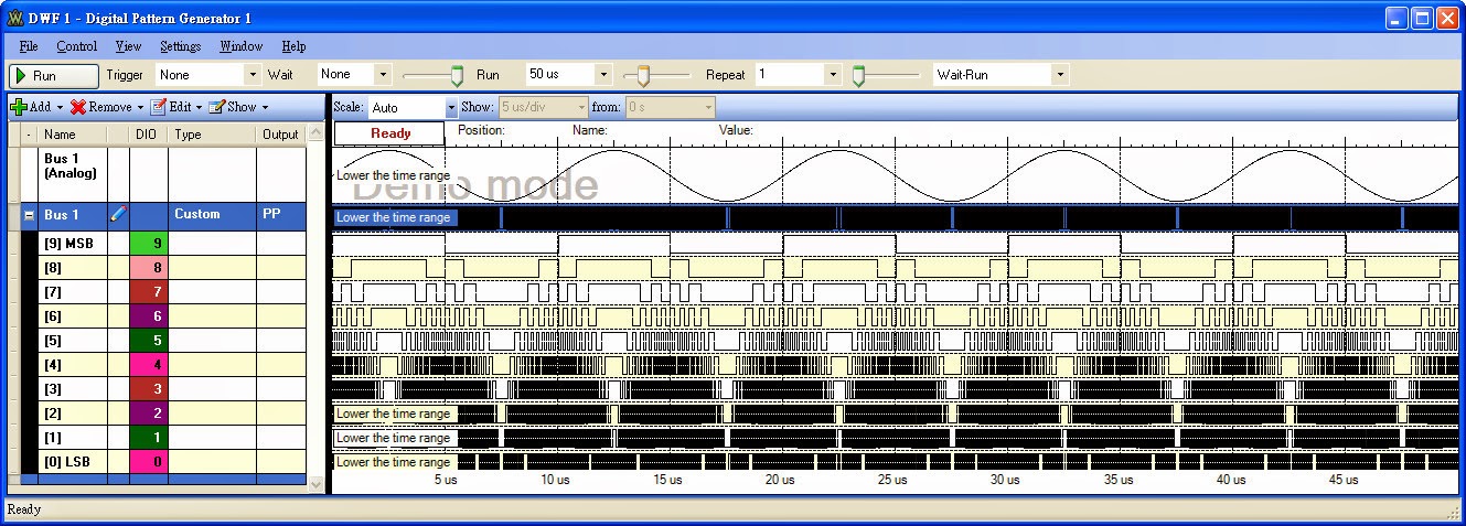
Digilent Analog Discovery Kit
Digilent Analog Discovery Kit(ADK in short) is an integrated instrument including
a. 2 channels oscilloscope
b. 16 channels logic analyzer
c. 2 channel arbitrary waveform generator(AWG)
d. 16 channels pattern generator
e. +/- 5V, 50mA power supply


2. TRM - pcb, IC list - overkill for provided components


4. personal application - BERT, long record pattern generator,
10-bit digital sinewave generation
Matlab code
==========
% pattern file generation for Digilent Analog Discovery Kit
% 2013/01 wjlee
clear;
close all;
%the file format for Waveforms's pattern generator
%line1(header): Bus 1,[9] MSB,[8],[7],[6],[5],[4],[3],[2],[1],[0] LSB
%line2: b0000000000,0,0,0,0,0,0,0,0,0,0
%line3: b0000000001,0,0,0,0,0,0,0,0,0,1
%line1025: b1111111111,1,1,1,1,1,1,1,1,1,1
reclen=1000; %the patgen record length(max=1024)
adcbit=10; %ADC resolution
dacbit=10; %DAC resolution
theta=0:2*pi/reclen:2*pi*(1-1/reclen);
adcfull=2^adcbit-1;
dacfull=2^dacbit-1;
amp=round(dacfull*(sin(theta)+1)/2);
plot(amp);
hold on;
grid on;
plot(amp,'r.');
axis([1 reclen 0 dacfull]);
%write data to file
disp(' ');
disp('Generate the "pgenw.csv" for Digilent Analog Discovery Kit Pattern Generator');
disp(' ');
%pgenw='pgenw.csv';
%fid1=fopen(pgenw,'w');
fid1=fopen('pgenw.csv','w');
if dacbit==10
fprintf(fid1,'Bus 1,[9] MSB,[8],[7],[6],[5],[4],[3],[2],[1],[0] LSB \n',' ');
ampbin=dec2bin(amp,10);
for i=1:reclen,
fprintf(fid1,'b%s,%s,%s,%s,%s,%s,%s,%s,%s,%s,%s \n',ampbin(i,:),ampbin(i,1),ampbin(i,2),ampbin(i,3),ampbin(i,4),ampbin(i,5),ampbin(i,6),ampbin(i,7),ampbin(i,8),ampbin(i,9),ampbin(i,10));
end
end;
fclose(fid1);
%if dacbit==9 then
% fprintf(fid1,'Bus 1,[8] MSB,[7],[6],[5],[4],[3],[2],[1],[0] LSB \n',' ');
%end;
%if dacbit==8 then
% fprintf(fid1,'Bus 1,[7] MSB,[6],[5],[4],[3],[2],[1],[0] LSB \n',' ');
%end;
==========
a. 2 channels oscilloscope
b. 16 channels logic analyzer
c. 2 channel arbitrary waveform generator(AWG)
d. 16 channels pattern generator
e. +/- 5V, 50mA power supply
2. TRM - pcb, IC list - overkill for provided components
Top side of the ADK PCB
Bottom side of the ADK PCB
3. software feature - FFT, SA, AWG, PG4. personal application - BERT, long record pattern generator,
10-bit digital sinewave generation
Matlab code
==========
% pattern file generation for Digilent Analog Discovery Kit
% 2013/01 wjlee
clear;
close all;
%the file format for Waveforms's pattern generator
%line1(header): Bus 1,[9] MSB,[8],[7],[6],[5],[4],[3],[2],[1],[0] LSB
%line2: b0000000000,0,0,0,0,0,0,0,0,0,0
%line3: b0000000001,0,0,0,0,0,0,0,0,0,1
%line1025: b1111111111,1,1,1,1,1,1,1,1,1,1
reclen=1000; %the patgen record length(max=1024)
adcbit=10; %ADC resolution
dacbit=10; %DAC resolution
theta=0:2*pi/reclen:2*pi*(1-1/reclen);
adcfull=2^adcbit-1;
dacfull=2^dacbit-1;
amp=round(dacfull*(sin(theta)+1)/2);
plot(amp);
hold on;
grid on;
plot(amp,'r.');
axis([1 reclen 0 dacfull]);
%write data to file
disp(' ');
disp('Generate the "pgenw.csv" for Digilent Analog Discovery Kit Pattern Generator');
disp(' ');
%pgenw='pgenw.csv';
%fid1=fopen(pgenw,'w');
fid1=fopen('pgenw.csv','w');
if dacbit==10
fprintf(fid1,'Bus 1,[9] MSB,[8],[7],[6],[5],[4],[3],[2],[1],[0] LSB \n',' ');
ampbin=dec2bin(amp,10);
for i=1:reclen,
fprintf(fid1,'b%s,%s,%s,%s,%s,%s,%s,%s,%s,%s,%s \n',ampbin(i,:),ampbin(i,1),ampbin(i,2),ampbin(i,3),ampbin(i,4),ampbin(i,5),ampbin(i,6),ampbin(i,7),ampbin(i,8),ampbin(i,9),ampbin(i,10));
end
end;
fclose(fid1);
%if dacbit==9 then
% fprintf(fid1,'Bus 1,[8] MSB,[7],[6],[5],[4],[3],[2],[1],[0] LSB \n',' ');
%end;
%if dacbit==8 then
% fprintf(fid1,'Bus 1,[7] MSB,[6],[5],[4],[3],[2],[1],[0] LSB \n',' ');
%end;
==========
FAST - Five hundred meter Aperture Spherical Telescope
 FAST In the Wikipedia
https://en.wikipedia.org/wiki/Five_hundred_meter_Aperture_Spherical_Telescope
The formal website of FAST
http://fast.bao.ac.cn/en/Receiver.html
The FAST cover frequency range from 70MHz to 3GHz with multi-beam, multi-band receiver

The comparison to Arecibo and FAST

The Feed Cabin Suspension System

sbKeyer Introduction and Assembly
sbKeyer
Introduction and Assembly
Introduction and Assembly
by Vincent Lee/bv3ue

Why I build this Kit ?
K3NG build a beauty code for
Arduino based Keyer and I think most of people is excited and want to try it
immediately. As an old flow, breadboard plug-and-play is the fastest way to
work for it. Yes, I went the old flow. As you can see in the following picture
- a breadboard, an Arduino Nano board, some resistors/capacitors/LED/Buzzer, some jumping
wires, some soldering for phone jack and rotary encoder. It takes 30 minutes to
1 hour to assembly then you can start to practice the CW code.

Figure
1 Breadboard assembly for the K3NG Keyer
Can we shortage for components in our trash
box ? Can we buy something wrong in the store ? Yes, it happened. We just take
time to drive out to buy something again or mail order to wait for days. Oscar/DJ0MY
had provided a nanoKeyer kit for us. (https://nanokeyer.wordpress.com/).
After the assembly, you need to install an Arduino Nano board, one suitable
case with some hole-drilling preparation then it is done. Is there someone to
provide a kit, and we just “plug-and-play” ? It seems the Martin/OK1RR provide
a detail information(http://www.ok1rr.com/index.php/technical-topics/122-the-tinykeyer)
to build and named it as tinyKeyer. Martin provides it as kit to the interested
people. Based on the same simplicity idea, I built my own and also provide as a
kit to the interested people. After receiving the built kit in a sturdy box,
you connect it with paddle and mini-USB cable to computer, then you can start
to tweak the code to meet your need. If you need the basic feature as command
line interface(CLI), memory macro and training practice. OK, that is what I
preset for you. You spare your time in hardware preparation and focus on
software tweaking and field usage.
Listing in the website, the features for
the K3NG keyer,
- CW speed adjustable from 1 to 999
WPM
- Up to six selectable transmitter
keying lines
- Programming and interfacing via
USB port (“command line interface”)
- USB
or PS2 Keyboard Interface for CW keyboard operation without a
computer
- Logging and Contest Program
Interfacing via K1EL Winkey 1.0 and 2.0 interface protocol emulation
- Optional PTT outputs with
configurable lead, tail, and hang times
- Optional LCD Display – Classic 4 bit
mode , Adafruit I2C RGB display and I2C Character Backpack or YourDuino
I2C LCD Display
- Up to 12 memories with macros
- Serial numbers
- CW keyboard (via a terminal
server program like Putty or the Arduino Serial program)
- Speed
potentiometer or rotary
encoder (speed adjustable with commands)
- QRSS
and HSCW
- Beacon
/ Fox mode
- Iambic
A and B
- Straight
key support
- Ultimatic
mode
- Bug
mode
- CMOS
Super Keyer Iambic B Timing
- Paddle
reverse
- Hellschreiber
mode (keyboard
sending, memory macro, beacon)
- Farnsworth Timing
- Adjustable frequency sidetone
- Sidetone disable / sidetone
high/low output for keying outboard audio oscillator
- Command
mode for using
the paddle to change settings, program memories, etc.
- Keying Compensation
- Dah
to Dit Ratio adjustment
- Weighting
- Callsign
receive practice
- Send practice
- Memory stacking
- “Dead
Operator Watchdog”
- Autospace
- Wordspace Adjustment
- Pre-configured
and Custom Prosigns
- Non-volatile storage of most
settings
- Modular code design allowing
selection of features and easy code modification
- Non-English Character Support
- CW
Receive Decoder
- Rotary
Encoder Speed Control
- Sleep
Mode
- USB
Mouse Support
- Mayhew
LED Ring Support
- Alphabet
Sending Practice
- QLF / “Messy” Straight Key
Emulation
- USB
Keyboard HID Interface (Keyer = keyboard for your
computer)
- Training
Module
We can’t compile all these features into an
Arduino Nano board with only 32KB flash memory and 2KB SRAM. To get a full
feature keyer, Arduino MEGA2560 or Teensy 3.2 is required.
The code I used is released at “2017.06.28.02”
to compile with Arduino 1.6.12.
What is the sbKeyer ? “sb” is the short name for small box or sturdy box
What is the sbKeyer ? “sb” is the short name for small box or sturdy box
I am not an experienced CW operator and also
not join the contest. So I added following features at “keyer_features_and_options.h”
to work for CW practice.
#define
FEATURE_COMMAND_LINE_INTERFACE
#define
FEATURE_MEMORIES
#define
FEATURE_TRAINING_COMMAND_LINE_INTERFACE
#define
FEATURE_ROTARY_ENCODER
The I/O pins definition for Paddle, rotary
encoder, PTT, LED, Buzzer etc. are defined at “keyer_pin_settings.h”
as
#define
paddle_left 2 //sbKeyer, PADDL left
#define
paddle_right 5 //sbKeyer, PADDLE right
#define
sidetone_line 4 //sbKeyer, connect a speaker for
sidetone
#define
tx_key_line_1 12 //sbKeyer, KEY
#define
ptt_tx_1 13 //sbKeyer,
PTT
#ifdef
FEATURE_COMMAND_BUTTONS
#define analog_buttons_pin A1 //sbKeyer, command button sense
#define command_mode_active_led 9 //sbKeyer, green LED
#endif
//FEATURE_COMMAND_BUTTONS
#ifdef
FEATURE_ROTARY_ENCODER
#define OPTION_ENCODER_HALF_STEP_MODE // Half-step mode?
#define rotary_pin1 10 //sbKeyer, CW Encoder Pin
#define rotary_pin2 11 //sbKeyer, CCW Encoder Pin
#define OPTION_ENCODER_ENABLE_PULLUPS // define to enable weak pullups.
#endif
//FEATURE_ROTARY_ENCODER
In addition, D3/D6/D7/D8/A3/A4(SDA)/A5(SCL)
is pulled out for future expansion. These pin assignment can be checked with
Figure 2 schematic.
The whole listing of “keyer_features_and_options.h”
and “keyer_pin_settings.h” is
shown in Appendix
The compilation log displayed the Flash
memory usage is 99% !!
|
Sketch uses 30,482 bytes (99%) of program storage space. Maximum is 30,720 bytes.
Global variables use 1,045 bytes (51%) of
dynamic memory, leaving 1,003 bytes for local variables. Maximum is 2,048 bytes
|
Schematic


Figure
2 sbKeyer schematic
The pins
assignment for the board are
1.
DIH/left and DAH/right
for paddle – D2 and D5
2.
PTT and KEY to
transceiver – D13 and D12
3.
CW and CCW for rotary
encoder – D10 and D11
4.
Command and
CW/Buzzer LED indicator – D9 and D4
a.
For someone need
the LED to indicate the CW activity but don’t want to hear the sound, the SWBUZ
jumper can work for that requirement. You can also use the command (\o) to
turn-off the CW activity to LED and buzzer.
b.
C1(10mF) and ASR is used to inhibit the programming capability to the
Nano board. When C1 is populated and ASM jumper is shorted, the Nano board
can’t be programmed thru the USB interface.
c.
R7 and de-bounce
capacitor over the rotary encoder is an option and they are not populated
PCB
PCB


The PCB board is fixed in the box with
sliding slot. No screw bot necessary. The front cover and back cover panel is
also prepared with PCB without further hole drilling and labeling necessary.
Bill of Material
Designators
|
Description
|
Quantity
|
R1, R2, R3,
R4, R6
|
10K, 0805
resistor(top code 103)
|
5
|
Q1, Q2
|
2N7002, SOT23
NCH MOSFET
|
2
|
R8, R9
|
1K, 0805
resistor(top code 102)
|
2
|
R5G, R5R
|
1K, 0805
resistor(top code 102)
|
2
|
R7
|
5K, 0805
resistor(option)
|
1
|
BRD1
|
Arduino Nano
board(CH340 USB to UART)
|
1
|
BUZZ
|
Piezo buzzer(match
the “+“ sign in PCB and buzzer)
|
1
|
C1
|
10uF,
capacitor with polarity(top code 106)
|
1
|
C2, C3, C4, C5
|
1nF, 0805
capacitor(top code 102)
|
4
|
C6A, C6B
|
47nF, 0805
capacitor for debounce(option)
|
2
|
ASR
|
Jumper to
inhibit the programming(short to inhibit)
|
1
|
PGND
|
Ground pin
|
1
|
RE1
|
Rotary encoder
with switch
|
1
|
GPIO
|
I/O pins pull-out
for experiment
- A3/A4(SDA)/A5(SCL) and D3/D6/D7/D8 |
1
|
LDCMD_GR
|
LED for Command(green)
and CW activity(red)
- stack together with socket |
1
|
LDBUZ_RED
|
1
|
|
PDL, PTT
|
Stereo phone jack
- 3 conductor jack with 2 break contacts (normal) and 2 auxiliary make contacts |
2
|
PCB
|
Main, front
and back panel PCB
|
3
|
Metal Box
|
60x46x20(LxWxH) mm Aluminum
box
|
1
|
Assembly
Instruction
1. Mount the backside and topside SMD
components
R1/R2/R3/R4/R6/R5G/R5R/R8/R9,
C1/C2/C3/C4/C5, Q1/Q2
2. Mount the Arduino Nano board
Solder the DIP pin and connect it
tightly with the main PCB, then the USB connector can align properly to the
front panel.
3. Mount the topside through hole
components
PTEST pin, PDL/PTT phone jack,
LEDSKT, Rotary encoder, Buzzer
4. Connect the rotary encoder to
front panel with bolt and washer, then slide the PCB into box track and mount back
panel.
5. A 30 minutes assembly video
will show in Youtube later time
Serial Command Line Interface (CLI) / CW
Keyboard
type what you want
the keyer to send (all commands are preceded with a backslash)
\? Help (requires FEATURE_SERIAL_HELP)
\# Play memory # (requires FEATURES_MEMORIES;
play memories 1 - 10)
\a Iambic A mode
\b Iambic B mode
\c Single Paddle mode
\d Ultimatic mode
\e#### Set serial
number to ####
\f#### Set
sidetone frequency to #### hertz
\g Bug mode
\h Toggle between CW and Hell sending (requires
FEATURE_HELL)
\i Transmit enable/disable
\j### Dah to dit ratio (300 = 3.00, do \j alone to
set to default)
\k CW Training
Module (requires FEATURE_TRAINING_COMMAND_LINE_INTERFACE)
\l## Set weighting
(50 = normal, do \l alone to set to default)
\m### Set Farnsworth speed
\n Toggle paddle reverse
\o Toggle sidetone on/off
\p#(#) Program
memory #
\q## Switch to QRSS mode, dit length ## seconds
\r Switch to regular speed mode
\s Status
\t Tune mode
\u Manual PTT toggle
\v Toggle potentiometer active / inactive (requires FEATURE_POTENTIOMETER)
\w### Set speed in WPM
\x# Switch to transmitter #
\y# Change wordspace to # elements (# = 1 to 9)
\z Autospace on/off
\+ Create prosign
\!## Repeat play memory
\|#### Set memory
repeat (milliseconds) (backslash and
pipe)
\* Toggle paddle echo
\` Toggle straight key echo
\^ Toggle wait for carriage return to send CW /
send CW immediately
\& Toggle CMOS Super Keyer Timing on/off
\%## Set CMOS Super Keyer Timing %
\. Toggle dit buffer on/off
\- Toggle dah buffer on/off
\~ Reset unit
\: Toggle cw send echo
\{ QLF mode on/off
\> Send serial number, then increment
\< Send current serial number
\( Send current serial number in cut numbers
\) Send serial number with cut numbers, then
increment
\[ Set Quiet Paddle Interruption
\= Toggle American Morse mode (requires
FEATURE_AMERICAN_MORSE)
\\ Immediately clear the buffer, stop memory
sending, etc.
Command Mode (press RE1 button to enter command mode
and press again to exit)
A Switch to Iambic A mode
B Switch to Iambic B mode
C Switch to Single Paddle Mode
D Switch to Ultimatic mode
E Announce speed
F Adjust sidetone frequency
G Switch to bug mode
H Set weighting and dah to dit ratio to defaults
I TX enable / disable
J Dah to dit ratio adjust
K Toggle Dit and Dah Buffers on and off
L Adjust weighting
N Toggle paddle reverse
O Toggle sidetone on / off
P#(#) Program a
memory
R#### Set serial number to ####
S Alphabet code practice (FEATURE_ALPHABET_SEND_PRACTICE)
T Tune mode
V Toggle potentiometer active / inactive
W Change speed
X Exit command mode (you can also press the
command button (button0) to exit)
Y#### Change
memory repeat delay to #### mS
Z Autospace On/Off
# Play a memory without transmitting
? Status
1. Speed in WPM
2. Keyer Mode (A = Iambic A, B = Iambic B, G
= Bug, S = Single Paddle, U = Ultimatic)
3. Weighting
4. Dah to Dit Ratio
Appendix
a. Files definition and usage
k3ng_keyer.ino : this is the main code; object declarations
for some hardware devices are included in this file
keyer.h : various declarations used in the
k3ng_keyer.ino code
keyer_debug.h : turns on debugging code; you probably
won’t ever have to touch this unless you’re deep in the code or someone on the
Radio Artisan group asks you
keyer_dependencies.h: Don’t touch this file. You’ll shoot your eye out.
keyer_features_and_options.h : configure the features you want
here
keyer_hardware.h : This is for defining custom or preset
configurations.
keyer_pin_settings.h : map the pins you’re using with
your hardware
keyer_settings.h : various settings for features; you
probably won’t need to touch this unless you’re a power user or want to tweak
stuff to enable debugging and post the debug logs for troubleshooting purposes
Some files for special hardware likes nanoKeyer, open_interface, tinyKeyer are preconfigured. For tinyKeyer, they are
keyer_features_and_options_tinykeyer.h
keyer_pin_settings_tinykeyer.h
keyer_settings_tinykeyer.h
You can
simply un-comment the definition over “keyer_hardware.h” to work them.
b. keyer_features_and_options.h
// red bold letter are the FEATURE opened
in sbKeyer
// compile time
features and options - comment or uncomment to add or delete features
// FEATURES add
more bytes to the compiled binary, OPTIONS change code behavior
// #define
FEATURE_COMMAND_BUTTONS //limited flash size, sbKeyer don't open this feature
#define
FEATURE_COMMAND_LINE_INTERFACE
#define FEATURE_MEMORIES
// #define
FEATURE_MEMORY_MACROS
// #define
FEATURE_WINKEY_EMULATION
// #define
FEATURE_BEACON
#define
FEATURE_TRAINING_COMMAND_LINE_INTERFACE
// #define
FEATURE_CALLSIGN_RECEIVE_PRACTICE
// #define
FEATURE_POTENTIOMETER
// #define
FEATURE_SERIAL_HELP
// #define
FEATURE_HELL
// #define
FEATURE_PS2_KEYBOARD
// #define
FEATURE_USB_KEYBOARD
// #define
FEATURE_CW_COMPUTER_KEYBOARD
// #define
FEATURE_DEAD_OP_WATCHDOG
// #define
FEATURE_AUTOSPACE
// #define
FEATURE_FARNSWORTH
// #define
FEATURE_DL2SBA_BANKSWITCH
// #define
FEATURE_LCD_4BIT
// #define
FEATURE_LCD_ADAFRUIT_I2C
// #define
FEATURE_LCD_ADAFRUIT_BACKPACK
// #define
FEATURE_LCD_YDv1
// #define
FEATURE_LCD1602_N07DH
// #define
FEATURE_LCD_SAINSMART_I2C
// #define
FEATURE_CW_DECODER
// #define
FEATURE_SLEEP
#define FEATURE_ROTARY_ENCODER
// #define
FEATURE_CMOS_SUPER_KEYER_IAMBIC_B_TIMING
// #define
FEATURE_DIT_DAH_BUFFER_CONTROL
// #define
FEATURE_HI_PRECISION_LOOP_TIMING
// #define
FEATURE_USB_MOUSE
// #define
FEATURE_CAPACITIVE_PADDLE_PINS
// #define
FEATURE_LED_RING
// #define
FEATURE_ALPHABET_SEND_PRACTICE
// #define
FEATURE_PTT_INTERLOCK
// #define
FEATURE_QLF
// #define
FEATURE_EEPROM_E24C1024
// #define
FEATURE_STRAIGHT_KEY
// #define
FEATURE_DYNAMIC_DAH_TO_DIT_RATIO
// #define
FEATURE_PADDLE_ECHO
// #define
FEATURE_STRAIGHT_KEY_ECHO
// #define
FEATURE_COMMAND_LINE_INTERFACE_ON_SECONDARY_PORT
#define
OPTION_PRIMARY_SERIAL_PORT_DEFAULT_WINKEY_EMULATION
// #define
OPTION_SUPPRESS_SERIAL_BOOT_MSG
#define
OPTION_INCLUDE_PTT_TAIL_FOR_MANUAL_SENDING
#define
OPTION_EXCLUDE_PTT_HANG_TIME_FOR_MANUAL_SENDING
// #define
OPTION_WINKEY_DISCARD_BYTES_AT_STARTUP
// #define
OPTION_WINKEY_STRICT_EEPROM_WRITES_MAY_WEAR_OUT_EEPROM
// #define
OPTION_WINKEY_SEND_WORDSPACE_AT_END_OF_BUFFER
#define
OPTION_WINKEY_STRICT_HOST_OPEN
#define
OPTION_WINKEY_2_SUPPORT
#define
OPTION_WINKEY_INTERRUPTS_MEMORY_REPEAT
//#define
OPTION_WINKEY_UCXLOG_9600_BAUD
// #define
OPTION_WINKEY_2_HOST_CLOSE_NO_SERIAL_PORT_RESET
// #define
OPTION_WINKEY_FREQUENT_STATUS_REPORT
#define
OPTION_WINKEY_IGNORE_LOWERCASE
// #define
OPTION_REVERSE_BUTTON_ORDER
#define
OPTION_PROG_MEM_TRIM_TRAILING_SPACES
#define
OPTION_DIT_PADDLE_NO_SEND_ON_MEM_RPT
// #define
OPTION_MORE_DISPLAY_MSGS
// #define
OPTION_N1MM_WINKEY_TAB_BUG_WORKAROUND
// #define
OPTION_WATCHDOG_TIMER
// #define
OPTION_MOUSE_MOVEMENT_PADDLE
// #define
OPTION_NON_ENGLISH_EXTENSIONS
// #define
OPTION_KEEP_PTT_KEYED_WHEN_CHARS_BUFFERED
// #define
OPTION_DISPLAY_NON_ENGLISH_EXTENSIONS
// #define
OPTION_UNKNOWN_CHARACTER_ERROR_TONE
// #define
OPTION_DO_NOT_SAY_HI
// #define
OPTION_PS2_NON_ENGLISH_CHAR_LCD_DISPLAY_SUPPORT
// #define
OPTION_PS2_KEYBOARD_RESET
// #define
OPTION_SAVE_MEMORY_NANOKEYER
#define OPTION_CW_KEYBOARD_CAPSLOCK_BEEP
// #define
OPTION_CW_KEYBOARD_ITALIAN
// #define
OPTION_CW_DECODER_GOERTZEL_AUDIO_DETECTOR
// #define
OPTION_INVERT_PADDLE_PIN_LOGIC
// #define OPTION_DIT_DAH_BUFFERS_OFF_BY_DEFAULT_FOR_FEATURE_DIT_DAH_BUFFER_CONTROL
// #define
OPTION_ADVANCED_SPEED_DISPLAY
// #define
OPTION_PROSIGN_SUPPORT
// #define
OPTION_RUSSIAN_LANGUAGE_SEND_CLI
#define
OPTION_DO_NOT_SEND_UNKNOWN_CHAR_QUESTION
c. keyer_pin_settings.h
/* Pins - you must
review these and configure ! */
#ifndef keyer_pin_settings_h
#define
keyer_pin_settings_h
#define paddle_left 2 //sbKeyer, Paddle left
#define paddle_right 5 //sbKeyer, Paddle right
#define tx_key_line_1 12 //sbKeyer, KEY(high = key down/tx on)
#define
tx_key_line_2 0
#define
tx_key_line_3 0
#define
tx_key_line_4 0
#define
tx_key_line_5 0
#define
tx_key_line_6 0
#define sidetone_line 4 // sbKeyer, connect a speaker for
sidetone
#define
potentiometer A0 // Speed
potentiometer (0 to 5 V) Use pot from 1k to 10k
#define ptt_tx_1 13 // sbKeyer, PTT ("push to
talk") lines
#define ptt_tx_2
0 // Can be used for keying fox transmitter, T/R
switch
#define ptt_tx_3
0 // These are optional - set to 0 if unused
#define ptt_tx_4 0
#define ptt_tx_5 0
#define ptt_tx_6 0
#define tx_key_dit
0 // if defined, goes active
for dit
#define tx_key_dah
0 // if defined, goes active
for dah
#ifdef
FEATURE_COMMAND_BUTTONS
#define analog_buttons_pin A1
#define
command_mode_active_led 9 //sbKeyer,
green LED
#endif
//FEATURE_COMMAND_BUTTONS
#ifdef
FEATURE_SIDETONE_SWITCH
#define SIDETONE_SWITCH 8
#endif
//FEATURE_SIDETONE_SWITCH
// rotary encoder
pins and options - rotary encoder code from Jim Balls M0CKE
#ifdef FEATURE_ROTARY_ENCODER
#define OPTION_ENCODER_HALF_STEP_MODE // Half-step mode?
#define
rotary_pin1 10 //
sbKeyer, CW Encoder Pin
#define rotary_pin2 11
// sbKeyer, CCW Encoder Pin
#define OPTION_ENCODER_ENABLE_PULLUPS // define to enable weak pullups.
#endif
//FEATURE_ROTARY_ENCODER
#ifdef
FEATURE_ALPHABET_SEND_PRACTICE
#define correct_answer_led 0
#define wrong_answer_led 0
#endif
//FEATURE_ALPHABET_SEND_PRACTICE
#ifdef
FEATURE_PTT_INTERLOCK
#define ptt_interlock 0 // this pin disables PTT and TX KEY
#endif
//FEATURE_PTT_INTERLOCK
#ifdef
FEATURE_STRAIGHT_KEY
#define pin_straight_key 52
#endif
//FEATURE_STRAIGHT_KEY
#if
defined(FEATURE_COMPETITION_COMPRESSION_DETECTION)
#define compression_detection_pin 13
#endif
//FEATURE_COMPETITION_COMPRESSION_DETECTION
#if
defined(FEATURE_SLEEP)
#define keyer_awake 0
#endif
#else
#error "Multiple pin_settings.h files
included somehow..."
#endif
//keyer_pin_settings_h
FAQ
Why the Keyer has no sound output ?
Please check
the sidetone mode is on or off by “\s” and use “\o” to toggle the sidetone
What happen to short-circuit the ASR pin ?
The
Arduino will not be programmed. If you try to upload the compiled Sketch, it
will alarm for “?” 10 times and display the programming failed.
How about to load the compiled HEX file to
Arduino Nano directly ?
You can
use the Xloader to work for it.
What features, options and pins assignment in
the sbKeyer ?
K3NG
provide different profile to work for nanoKeyer, tinyKeyer, open interface
Keyer etc. You can uncomment the hardware information in “keyer_hardware.h” to
work for different hardware. For sbKeyer, a Python script is provided to do the
modification to the latest K3NG release. After running the Python script, the
original “*.h” will move to “*.h_orig”
Why the USB link broken(COM port disappeared)
sometimes with connection to the transceiver ?
You need install
the latest CH340 driver to solve it.
What
feature I can open in the “keyer_features_and_options.h” ?
The memory size for different Arduino-liked
board are different. For Nano board, you can't open the CLI and WINKEY feature same time. With MEGA2560 or Teensy 3.2, you can open all the features, but you need check the conflict for different logger software.
How to check the CLI(Command Line Interface) ?
Use a
terminal emulator program(putty
or realterm). In
Arduino IDE, you can use the “Tools\Serial Monitor” with setting as N81/115200
baud/CR+NL. Type “\s” to see the current Keyer setting
and “\k” to enter training mode.
Where is the material for DIY ?
manual
schematic and pcb picture
Gerber files
K3NG codes and precompiled HEX file
CH340 driver
Where is the material for DIY ?
manual
schematic and pcb picture
Gerber files
K3NG codes and precompiled HEX file
CH340 driver
訂閱:
文章 (Atom)